Home  5  Books  5  GBEzine  5  News  5  HelpDesk  5  Register  5  GreenBuilding.co.uk
Not signed in (Sign In)

Categories


Green Building Bible, Fourth Edition
Green Building Bible, fourth edition (both books)
These two books are the perfect starting place to help you get to grips with one of the most vitally important aspects of our society - our homes and living environment.

PLEASE NOTE: A download link for Volume 1 will be sent to you by email and Volume 2 will be sent to you by post as a book.

Buy individually or both books together. Delivery is free!


powered by Surfing Waves


Vanilla 1.0.3 is a product of Lussumo. More Information: Documentation, Community Support.

Welcome to new Forum Visitors
Join the forum now and benefit from discussions with thousands of other green building fans and discounts on Green Building Press publications: Apply now.


    • CommentAuthorlineweight
    • CommentTimeSep 20th 2023
     
    Posted By: Doubting_Thomas
    Posted By: lineweightThe conductivity of steel is such that we can pretty much ignore the length of any heat path through the steel, or the cross-sectional area perpendicular to the heat paths.


    I don't quite get what you are driving at in this statement but what you are describing generally is the difference between what are called linear (psi value, W/m.K) and point (chi value, W/K) thermal bridges.

    There is a distinction in units, but also in the way that they are remedied. A linear thermal bridge can usually be resolved through adding other layers in the wall build-up, whereas a point thermal bridge will usually, by necessity penetrate through all these layers (unless thermally broken with a structural pad as described in the posts above) and is thus often harder to design out.

    Others can probably comment on their thermal equivalence or otherwise (I'm not convinced), but I'm struggling to see why you'd want to describe them in the same way when they aren't likely to be used for the same thing in reality.


    I'm picking up on comments from WillinAberdeen further up the thread, where he (I think) is making the point that a material such as steel has such a high conductivity that we can effectively ignore things we'd otherwise take into account. For example, just looking at simple U-value, for an insulative material doubling its thickness would have a significant effect, but doubling the thickness of a plate of steel would not have a significant effect on the rate of heat loss.

    If I understood properly, I think WillinAberdeen's point was that it's the surface area of steel in contact with air either side of the thermal bridge that becomes the most significant factor. Much more significant than the volume of steel that all heat paths have to travel through in order to get from the "warm" surface area to the "cold" surface area.

    Hence my thought experiment above, which is my way of testing that I have understood this correctly (and I might not have). Yes we might commonly measure one of those as a linear bridge and one as a point bridge, but I'm asking whether it's correct that we'd come up with a similar result for each scenario (measured in total heat loss for the entire assembly).

    I think that in the case of the wall with the beam running parallel with the brickwork, we could calculate it by working out a U-value for the brickwork portion, and a U-value for the steel-beam portion, and then multiplying by the relevant areas.

    In the case of the wall with the beam perpendicular, we can work out a U-value for the brickwork, but we can't do the same for the steel beam, we need to work out a chi value, but this is much more complicated to arrive at (and I think basically needs some kind of finite element analysis modelling).

    And this comes back to the original question/problem of my thread, because if I'm trying to make a broad judgement on how to deal with steel columns penetrating an insulation layer, it's not a simple calculation, it needs some quite complex modelling to quantify the heat loss and how much difference a certain insulation strategy will have. Therefore me (not having the resources to do that kind of modelling) poking around for a way to decide what's "sensible" to do.
    • CommentAuthorGreenPaddy
    • CommentTimeSep 20th 2023
     
    Lineweight, does the simple calculation I suggested above not give enough information ..."to decide what's the sensible thing to do"? Pursuing a super accurate answer to 3 decimal places with a fancy model doesn't feel like a sensible use of time.

    The quantity of steel outwith the thermal envelope only matters in that the more steel, the closer the steel will stay to the adjacent outside air temp. ie. lots of steel, and it will not be influenced by the heat coming from inside. But the heat flow would, in simple terms, be fixed with an assumed (guessed) temp differential, creating the energy driving force.
    • CommentAuthorlineweight
    • CommentTimeSep 20th 2023
     
    Posted By: GreenPaddyLineweight, does the simple calculation I suggested above not give enough information ..."to decide what's the sensible thing to do"? Pursuing a super accurate answer to 3 decimal places with a fancy model doesn't feel like a sensible use of time.

    The quantity of steel outwith the thermal envelope only matters in that the more steel, the closer the steel will stay to the adjacent outside air temp. ie. lots of steel, and it will not be influenced by the heat coming from inside. But the heat flow would, in simple terms, be fixed with an assumed (guessed) temp differential, creating the energy driving force.


    Yep sorry I didn't respond to that earlier, I guess I was hoping someone else with a better grasp of building physics would respond with comment on whether it made sense!

    You basically said:

    *******
    Simple formula of ... heat flow = (k x Area x delta T) / length of flow path

    heat flow (W) = 50 (W/mK) x 0.005(m2) x 10(oC) / 0.6(m)

    assuming 200x150 "H" steel post of 10mm thick plate steel
    assuming ground 10oC and inside 20oC
    assuming 600mm from post base to above insulation

    heat flow would be = 4W
    ******

    As I understand it, the area you are using here is the cross-sectional area of the steel column, is that right? And then the "length of flow path" is the length of the column insulated from either the indoor or outdoor air.

    So the amount of heat I am losing is proportional to the cross-sectional area and the length of heat path.

    Double the cross sectional area, and the heat loss is doubled. Half the length of flow path, and the heat loss is also doubled.

    This ignores how much column is projecting into the room or out into the cold air.

    That is how I previously would have visualised it, but my understanding of WillinAberdeen's comments, is that this is not right.

    I think that's because the amount of heat conducted at the surface boundaries between the steel and air, on each side, is really the limiting factor. So the 4W you came up with; this is the heat flow ignoring those surface boundaries, so would be the heat flow with a kind of infinite projecting length of steel either side, or something like that, but in fact the actual heat flow will be less, and heavily determined by the amount of steel surface area in contact with the air.

    How those numbers work out though, I don't know.
    0.5m of projecting steel means it's actually 3.8W and 1m of projecting steel means 3.9W?
    or
    0.5m of projecting steel means it's actually 2W and 1m of projecting steel means 3W?
    or
    0.5m of projecting steel means it's actually 0.2W and 1m of projecting steel means 0.4W?
    •  
      CommentAuthordjh
    • CommentTimeSep 20th 2023
     
    Posted By: lineweightdoubling the thickness of a plate of steel would not have a significant effect on the rate of heat loss
    That's true but it does matter in some situations. In the case of a steel column standing on cold ground for example, the rate of heat loss depends on the cross-sectional area that is in contact with the cold ground, so doubling the thickness of an I-beam would double the surface area and thus the heat loss (except that beams stood on end often have a flat plate welded to the end to connect them to the ground that vastly expands the surface area anyway!)
  1.  
    I wrote a long reply last week and the forum software crashed before it posted :-( here is what I remember of it:

    Love the thought experiment. The first example reminds me of sticking a skewer through a potato to make it bake quicker (worth trying IRL!)

    The second example is like having 1920s steel window frames, bridging from inside to outside without thermal breaks. They definitely sweat, and many people seem prepared to spend £ now to specify new window frames to be thermally broken instead of plain steel, even if the total Watts lost is not very many. But that's a cost/benefit for the client/project to decide depending how high-spec the project is (as your OP question and GP's reply).

    Seems to me that the most significant heat transfer resistance (insulation if you like) is the surface film resistance Rsi/Rso of the steel where in contact with the air. The two examples have different amounts of area exposed to air on the top/bottom surface.
    In the 'skewer' example the flanges of the I beam act like the fins you get on the back of steel radiators. Note how thin those are IE they aren't bothered about the thermal resistance or cross section of the steel, so long as the air contact is good.

    Cladding the exposed steel column in concrete would help cover up the 'fins' (reduce air contact area) and you could wrap/stick some insulation round the concrete at low cost?
    • CommentAuthorlineweight
    • CommentTimeSep 21st 2023
     
    Posted By: WillInAberdeenSeems to me that the most significant heat transfer resistance (insulation if you like) is the surface film resistance Rsi/Rso of the steel where in contact with the air. The two examples have different amounts of area exposed to air on the top/bottom surface.


    Yes, you have spotted a problem with my thought experiment in that the top/bottom surfaces of the flange are not exposed to the air in my "parallel" version. I should maybe have drawn it as a simple steel plate beam with negligible surface area top and bottom. Would we then be looking at similar amounts of heat loss in each case?


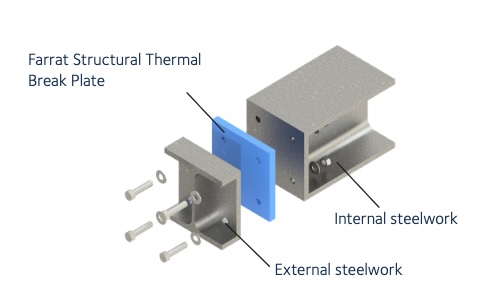
    Something I don't quite get: if the cross-sectional area of steel is not really significant, then how do thermal break plates work?

    Because although there's an insulating material between the end plates of the steel members, the two steel members are still connected by steel bolts. So once the bolts are installed, there's still a direct heat path, all through steel. I'd wondered if it relies on insulated washers, but these never seem to be mentioned.
      Screenshot 2023-09-21 at 12.05.46.jpg
    •  
      CommentAuthordjh
    • CommentTimeSep 21st 2023 edited
     
    Stainless bolts already mentioned. edit: much less thermally conductive than mild steel.
    • CommentAuthorlineweight
    • CommentTimeSep 21st 2023 edited
     
    Lower tensile strength though. I've not yet seen stainless bolts mentioned as part of the spec for any of these systems - but maybe that will be revealed on further enquiry.
    •  
      CommentAuthordjh
    • CommentTimeSep 21st 2023
     
    • CommentAuthorlineweight
    • CommentTimeSep 21st 2023
     
    That Schoeck pdf looks quite thorough and I'll have a read through of it. I note they distinguish between carbon/stainless steel bolts in the thermal break type assemblies.

    Earlier today I was looking at stuff from Farrat, eg

    https://farrat.com/wp-content/uploads/2023/04/STB-TP-Want-less-bounce-in-your-balcony-technical-report.pdf

    Which is rather less clearly set out. They don't seem to specify the material used for the bolts in their calculations.

    Likewise in the various Farrat and Armatherm details here:

    https://tools.bregroup.com/certifiedthermalproducts/display.jsp?id=3590&st=2&sst=0&pt=3&jt=7

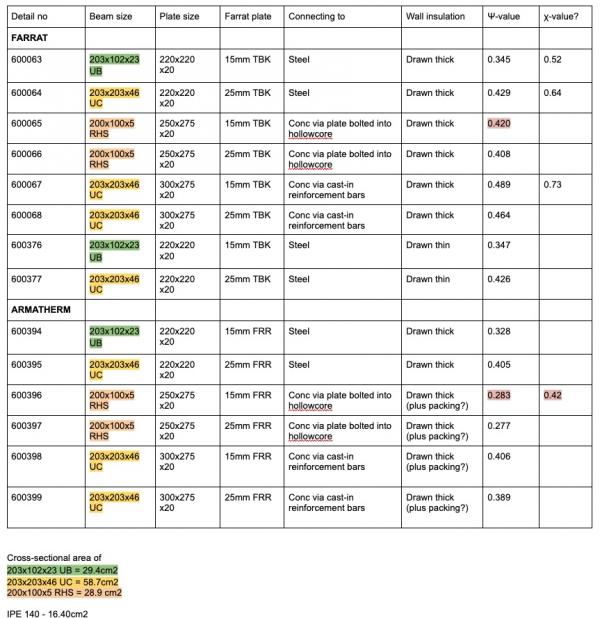
    but it's quite interesting to look at those, and see how the heat loss seems to be quite dependent on the size of the steel members, more so than on the thickness of the thermal break plates.

    I made this table for myself to get my head around what was being shown in each case.
      Screenshot 2023-09-21 at 23.21.26.jpg
Add your comments

    Username Password
  • Format comments as
 
   
The Ecobuilding Buzz
Site Map    |   Home    |   View Cart    |   Pressroom   |   Business   |   Links   
Logout    

© Green Building Press