Home  5  Books  5  GBEzine  5  News  5  HelpDesk  5  Register  5  GreenBuilding.co.uk
Not signed in (Sign In)

Categories


Green Building Bible, Fourth Edition
Green Building Bible, fourth edition (both books)
These two books are the perfect starting place to help you get to grips with one of the most vitally important aspects of our society - our homes and living environment.

PLEASE NOTE: A download link for Volume 1 will be sent to you by email and Volume 2 will be sent to you by post as a book.

Buy individually or both books together. Delivery is free!


powered by Surfing Waves


Vanilla 1.0.3 is a product of Lussumo. More Information: Documentation, Community Support.

Welcome to new Forum Visitors
Join the forum now and benefit from discussions with thousands of other green building fans and discounts on Green Building Press publications: Apply now.


  1.  
    I'm posting this because I can't find a past answer to this question on here (having looked through all 30 threads containing the term 'flat roof' in title) or elsewhere.

    In the attached photo (of my own handiwork), what I'm unclear about is:

    how to make the insulation continuous between the warm flat roof construction and the vertical rear wall. In my drawing, there's a big gaping cold bridge between the fascia board and the inside.

    I can see a couple of options, but is there a 'best practice' for this fairly common problem statement?

    All the manufacturer's details show just one plane of detail - the warm flat roof, or a timber frame wall, there is a paucity of details showing the joins!

    Options I've come up with:

    1) Simple but probably won't work - Add a chunk of PIR at the end of the joists to make it wrap around - and hope that the fascia can be attached to that through to the joist end

    2) Kinda complicated - add a modest depth of insulation to the end of the joists (say, 20mm) so that the fascia can be screwed through into the joist ends still; then place 150mm or more inbetween the joists where the joists overhang; then insulate the external side of the wall plate atop the stud wall.

    (also, welcome any constructive criticism on any other elements of the detail)
      thumbnail.jpeg
    •  
      CommentAuthordjh
    • CommentTimeMar 14th 2023
     
    I'm not sure what the red line is? Nor whether the joists are exposed in the room or if there is some kind of ceiling?

    Anyway, the wall insulation needs to go up and meet the roof insulation. There are two main thermal bridges through its path. The wall plate and the joists. The wall plate could be made of some strong insulation material I suppose but that would likely be expensive. Which of the upright studs is the load-bearing one? Normally it's the inside one, so if we assume that then the wall plate could be moved inboard so it leaves a clear space for the insulation to pass upwards outboard of it. The joists passing through the rising insulation are probably a tolerable repeating thermal bridge; it all depends on exactly what number you're trying to achieve. You can make the wall insulation thicker within the joist area; full-fill out to the end of the joists maybe. Are the ends of the joists exposed or is there a soffit?
  2.  
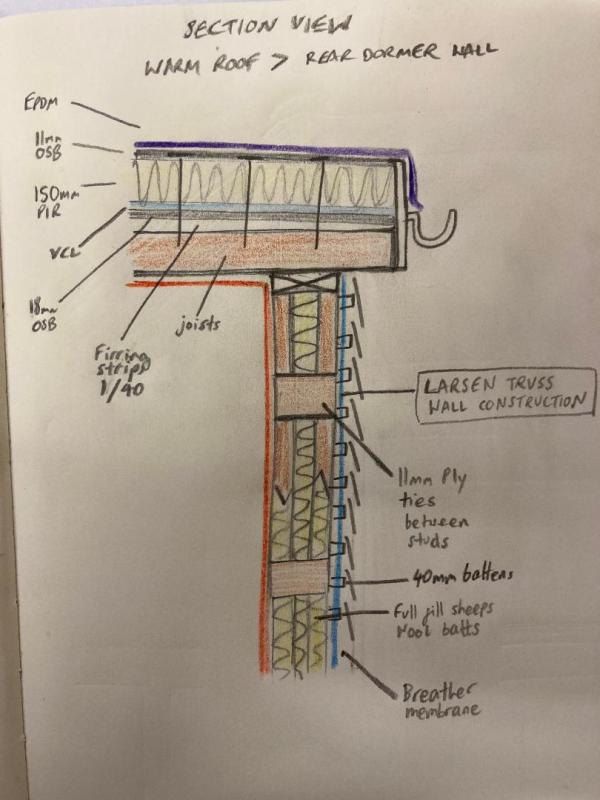
    Posted By: djhI'm not sure what the red line is? Nor whether the joists are exposed in the room or if there is some kind of ceiling?


    red line is to show the a/t line; yes there'll be some kind of ceiling and wall lining.

    Anyway, the wall insulation needs to go up and meet the roof insulation. There are two main thermal bridges through its path. The wall plate and the joists... The joists passing through the rising insulation are probably a tolerable repeating thermal bridge; it all depends on exactly what number you're trying to achieve.


    Yes, exactly. I'm aiming for AECB standard, not quite Enerphit.

    The wall plate could be made of some strong insulation material I suppose but that would likely be expensive.


    Do you mean something like foamglas or perinsul?

    Which of the upright studs is the load-bearing one? Normally it's the inside one, so if we assume that then the wall plate could be moved inboard so it leaves a clear space for the insulation to pass upwards outboard of it.

    yes, makes sense.

    You can make the wall insulation thicker within the joist area; full-fill out to the end of the joists maybe. Are the ends of the joists exposed or is there a soffit?


    The ends will not be exposed - there'll be a soffit. Had considered placing insulation on end of and underside of joist - the challenge is just about ensuring the fascia and guttering can still be secured through to the joists...
    • CommentAuthorGreenPaddy
    • CommentTimeMar 14th 2023
     
    Maybe something like this?

    Ceiling Joists don't have to run through. Insert end trimmer in timber to make a robust sandwich, into which the facia can be fixed. That's outside the insulation envelope.
    Insert insulation between the ceiling joists directly above the wall head.
    Add a cover layer of insulation over the joist tails and the wall head binder, with a batten fixed over that to give you a soffit fixing.

    Cat number one skinned. More cats for skinning no doubt :bigsmile:
  3.  
    Posted By: GreenPaddyMaybe something like this?

    Ceiling Joists don't have to run through. Insert end trimmer in timber to make a robust sandwich, into which the facia can be fixed. That's outside the insulation envelope.
    Insert insulation between the ceiling joists directly above the wall head.
    Add a cover layer of insulation over the joist tails and the wall head binder, with a batten fixed over that to give you a soffit fixing.


    thanks GreenPaddy, that's really helpful
    •  
      CommentAuthordjh
    • CommentTimeMar 14th 2023
     
    Posted By: number_thirty_threeDo you mean something like foamglas or perinsul?
    No, Compacfoam or another of the more dense EPS products.

    Posted By: number_thirty_threered line is to show the a/t line
    Why isn't the airtight line also the VCL?

    Posted By: GreenPaddyCeiling Joists don't have to run through.
    That's probably true as long as the overhang isn't too much. My structural engineer insisted on sprockets underneath a 600 mm overhang. But if they don't and if the wall plate is moved inboard then the whole thing simplifies to the existing wall insulation being carried straight up to meet the roof insulation. No extra faffing required.
  4.  
    Posted By: number_thirty_threered line is to show the a/t line
    Why isn't the airtight line also the VCL?

    Because in all warm roof construction details I have seen, there's a VCL on the top of the structural deck under the insulation. And I couldn't see how on earth it would be possible to tie that into the internal a/t layer on the walls (not just that rear wall but all the internal adjoining walls... so then thought perhaps better to have an internal a/t layer that is fully continuous as well.
    • CommentAuthorGreenPaddy
    • CommentTimeMar 15th 2023
     
    Your VCL needs to be continuous, I would argue, to meet the wall VCL. No need for two layers. The VCL at your red line is the correct place. There's no moisture being generated above that red line for any other layer to control. The VCL should pretty much always be as far in to the building (warm side) as poss, though usually outboard of service battens, so services don't penetrate it.

    Why do manuf details show it immed under the roof deck??? They don't know what your detailing will be, so show it to make sure you know it is BELOW the insulation layer. You can move it further inboard if you wish, if it suits your detail. I've seen arch's with the VCL above joists, and then they wrap the VCL over the joist ends and back in again, putting the VCL at the joist ends outside the insulation - wrong.
  5.  
    Posted By: GreenPaddyYour VCL needs to be continuous, I would argue, to meet the wall VCL. No need for two layers. The VCL at your red line is the correct place. There's no moisture being generated above that red line for any other layer to control. The VCL should pretty much always be as far in to the building (warm side) as poss, though usually outboard of service battens, so services don't penetrate it.

    Why do manuf details show it immed under the roof deck??? They don't know what your detailing will be, so show it to make sure you know it is BELOW the insulation layer. You can move it further inboard if you wish, if it suits your detail. I've seen arch's with the VCL above joists, and then they wrap the VCL over the joist ends and back in again, putting the VCL at the joist ends outside the insulation - wrong.


    That's really helpful GreenPaddy - thanks. ISWYM about being able to move it inboard - makes perfect sense. It's one of those situations where I've grasped some of the principles of this stuff - continuous layer of insulation and vcl but not quite got the confidence to ignore a manufacturer's detail!
Add your comments

    Username Password
  • Format comments as
 
   
The Ecobuilding Buzz
Site Map    |   Home    |   View Cart    |   Pressroom   |   Business   |   Links   
Logout    

© Green Building Press